Train Sheet Issue 192 is 16 pages and was published 3/29/22.
It was emailed to members who have chosen email delivery on 3/30/22.
Some email services are making emails from us as SPAM. If you don't see our emails in your in box, please check your spam folder. If it is in your spam folder please mark it as "not spam" and it should then move to your inbox and you should get future emails OK. If you still have a problem, please send email to webmaster@wplives.org so we can help you get on board!
It was USPS mailed on 3/31/22.
PDF file of Train Sheet 192 is available HERE!
Articles in this issue:
More photos related to What the HECK is a CONTACTOR? article
Click on an image to get full-screen image...
All photos by Greg Elems from SP 2873
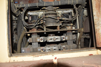
Photo 4753
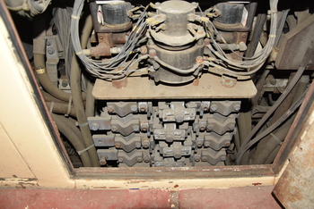
Photo 4752
Cam switch contactor for the traction motors.
That is what you hear clicking when you go from power to dynamic brakes.
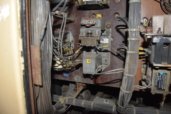
Photo 4758
The above photo depicts BR (dynamic Braking Relay), TDS (Time Delay Sanding) and PCRA (Pneumatic Control Relay), among other relays. As with most relays, these are named for the systems/components with which they interact and the circuits they affect. Brake Relay controls the functioning of the change over from power to dynamic braking the opening and closing of Brake Relay's various interlocks energizes or de-energies the proper circuits. Time Delay Sanding works with the automatic sanding function, and applies a timed application of sand to the selected direction of travel (forward or reverse sanding valves) when wheel creep or wheel slip is detected. The Pneumatic Control Relay works in conjunction with the Pneumatic Control Switch, de-energizing the Engine Run relay to drop the load and put any locomotives in consist in idle following a penalty air application.
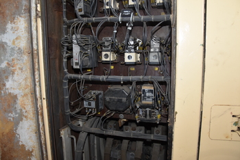
Photo 4759
The photo above depicts the relays GR (Ground Relay), FPR (Fuel Pump Relay), GFR (Generator Field Relay), LRC (Load Regulator Contactor) and PCR (Pneumatic Control Relay), among others. These relays open and close a variety of interlocks to control locomotive functions, and relays are generally named per their respective systems and devices and the operations they perform. For example, Fuel Pump Relay takes input from the starting and engine control circuits to close the circuit that powers the fuel pump.

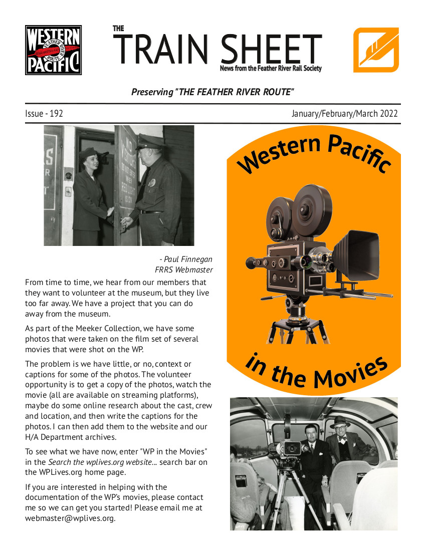
Photo 4764
These are the thermal switches that control the radiator shutter and cooling fans as well as the hot engine alarm, they are connected to temperature probes on the first group of radiators.

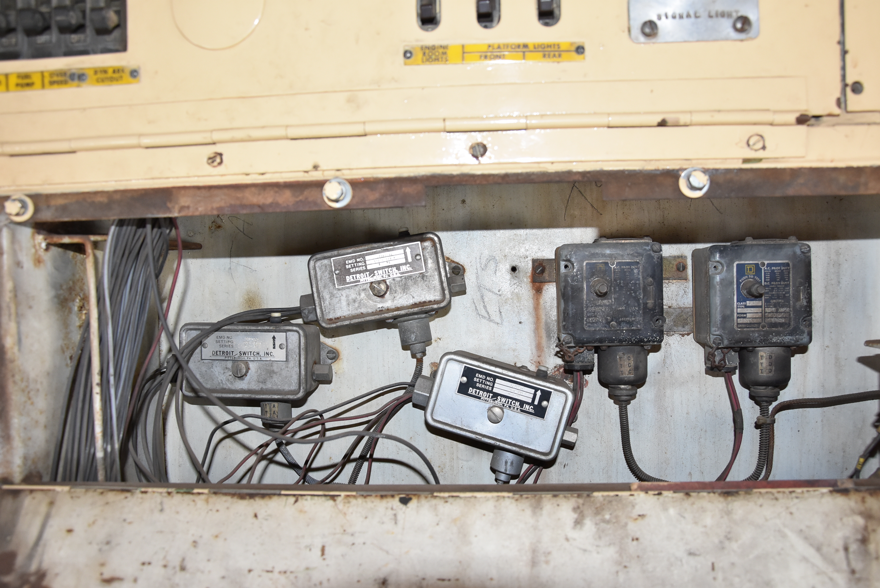
Photo 4765
Fuses for Electrical components within the locomotive

Fuses-Knife Switches and Circuit Breakers
Main battery disconnect (large knife switch) and more fuses for electrical components
(note: the starting fuse has been removed)
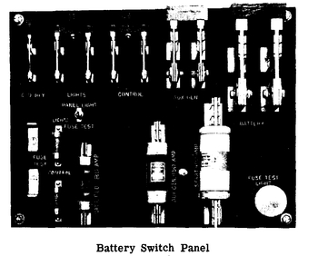
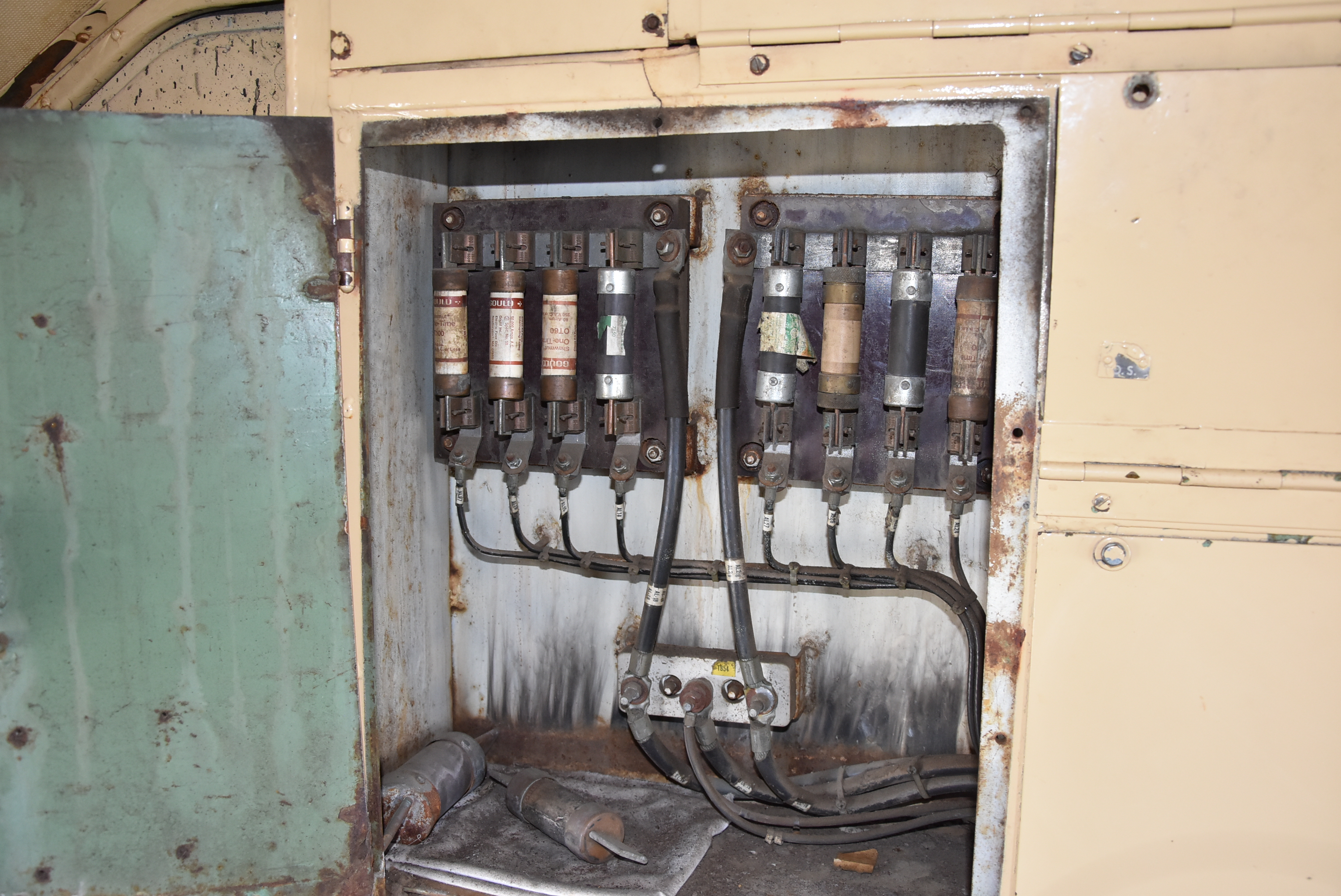
Image from WP OPERATING MANUAL GP9 LOCOMOTIVES of the Fuses-Knife Switches and Circuit Breakers
Located on the cab side of the electrical control cabinet, are the following fuses and knife Switches:
1. Ground Relay Knife Switch
2. Main "Lights" Switch
3. Main "Control" Switch
4. Auxiliary Generator Switch
5. Main Battery Switch
6. 30 Amp. Control and Light Fuses
7. 80 Amp. Battery Field Fuse
8. 150 or 250 Amp. Auxiliary Generator Fuse
9. 400 Amp. Starting Fuse