SN Operation through the Oakland Hills
By Robert A. Campbell, Sr.Updated and corrected August 28, 2011
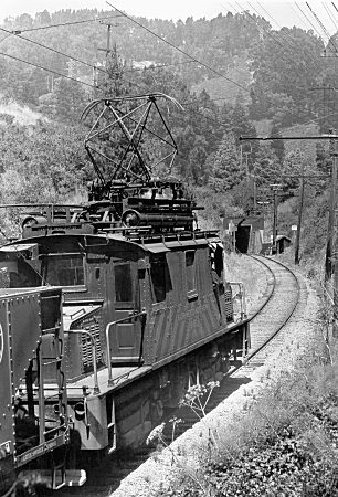
The first SN substation after leaving 40th and Shafter Eastbound was at Eastport, the Eastern portal of the tunnel. It had two 1,000 horsepower motor-generator sets because power use could be quite large as freight trains worked their way up the heavy grades and through the Berkeley Hills. In some places, the tunnel is referred to as the "tunnel under Redwood Peak", however it's actually under a saddle mid-way between to peaks, Round Top to the North and Redwood Peak to the South.
The Pacific Gas & Electric Company used a demand meter to calculate the SN's power bill. These meters measure maximum current drawn over predetermined time intervals and total kWh used over the monthly billing cycle. The higher the current drawn during any given interval, the greater the price per kWh for the month. In order to minimize its power bill in the post-WWII years, the SN instituted a system of "power waits" to take advantage of the automatic resetting to zero of the meter's load measuring apparatus at the end of each demand interval. The load arm moves up while power is drawn, forcing up the indicating arm, and the greater the current, the faster and further it moves up. While the load measuring arm resets automatically at the end of each interval, the indicator is reset manually only when the meter is read at the end of the billing cycle.
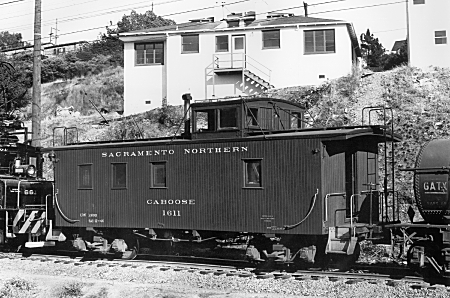
William T. Larkins photo; Robert A. Campbell, Sr., collection.
At Eastport, the demand interval was 20 minutes, and by requiring "power waits", the SN spread the measurement of a train's current draw between two or more intervals, which would make a train's total overall demand appear as low as possible, keeping the price of each kWh at a low rate. The rules for power waits are found in employee's timetable # 25 of September 27, 1953. Power waits aren't mentioned in #23 of April 20, 1947. #24 wasn't available to your author, so determining precisely when this policy began wasn't possible.
While waiting, all current draw from locomotives was halted by lowering pantographs, because it was cheaper to pay a crew to do nothing than to exceed the power allocation. During off-peak house, between 11 PM and 6 AM, and on Sundays and holidays power waits were not required. In order to understand better power usage and the complex rules the SN instituted regarding controller and train operation to take advantage of the demand cycle, it's necessary to digress a little and discuss control system design, operation, and usage.
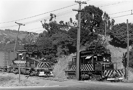
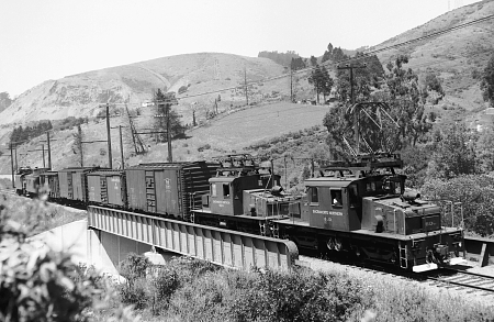
William T. Larkins photo; Robert A. Campbell, Sr., collection.
When starting a 600v passenger car, the motors are operated in series during the first part of the controller's sequence. As speed increases, the motors generate electricity internally, which is opposite to the polarity of that from the trolley wire. Eventually this "back pressure" rises to equal that being forced into the motors, limiting the maximum rotational speed of the motor (and, therefore, train speed). Since the motors are in series, once all accelerating resistance is cutout of the circuit there is only 300v across each motor, running them at half their designed speed.
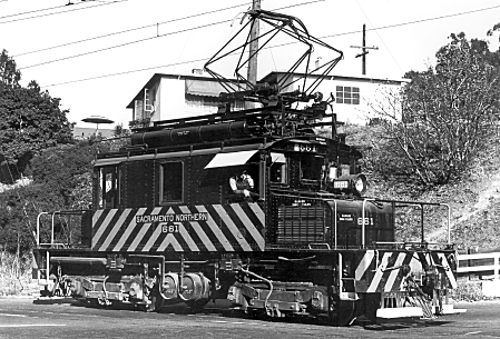
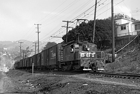
William T. Larkins photo; Robert A. Campbell, Sr., collection.
When the motorman moves the controller through transition, the motors are reconnected so that they are in parallel. This increases the impressed trolley voltage to a value which overcomes the back pressure, in turn making the motors run faster -- until the back pressure again rises to equal the trolley voltage. In the last point on the controller, the motors are now connected to 600v and run at their full design speed, called the "balancing speed". This re-connection scheme provides for two running speeds, known as "series" and "parallel", with "transition" being the change from one to the other.
This is the simple version because, except for two-motor cars, in "series" the motors are actually wired in two permanently connected parallel pairs, and it is these pairs which are connected in series and parallel. It also means that there is the possibility for obtaining three running speeds: "full series", in which all four motors are actually connected in series, "series-parallel" which is the same as the "series" described above; and "parallel", which is the same as "parallel", also above. Whether or not all three speeds were used depends on whether the operating company was willing to pay for the extra switchgear necessary for the third running speed. Typically, three speeds were unnecessary for passenger cars while locomotives frequently had all three.
On 1200v, the situation becomes a little confusing. After experimenting motors designed and wound for 1200v in the latter half of the first decade of the 20th century, the interurban industry and its suppliers settled on motors designed for 600v and insulated for 1200v. This was mostly cost-driven because it allowed for less engineering work, fewer designs, and less extensive parts inventories (for purposes of discussion here, 1200v = 1500v).
For dual-voltage operation, passenger cars such as the South End cars used a manual change-over switch which was operated only at 40th and Shafter and Union Station in Sacramento. It's wired to provide series-parallel and parallel operation when set for 600v and full-series and series-parallel operation on 1200v.
With locomotives, many operating companies were willing to pay for the extra switch gear to take advantage of three running speeds because it provides greater speed flexibility when hauling freight cars. However, with 600/1200 dual-voltage locomotives, all three of the running speeds are available only when the change-over switch is set for 600v. When set for 1200v, there is only full-series and series-parallel, which keeps the voltage across each motor to the design voltage of 600v. All of the SN's dual-voltage locomotives followed this practice.
Of all the SN's locomotives, only 603 and 604 were fully MU-capable (control, power, and air brakes). When these two were operating in multiple-unit control, the pantograph of the second locomotive was kept in the down position. Only one current collector up at a time was a requirement for both passenger and freight trains and was necessitated by the 600-1500 volt section insulators between the Key System's and PG&E's 600v trolley wires in Oakland and Sacramento (1500v can wreak havoc if it gets into a 600v system). Two locomotives were required to have a minimum of three air compressors operating, so all other locomotives had to operate with their pans up to power their air compressors. Locomotives 660 and 661 had MU connections only for air brakes, not control, and locomotives 650-654 and 670 were not MU-equipped (neither control nor air brakes).
Series-parallel could be used when 643 and 644 worked together in situations where two other locomotives were required to run in full-series. If they headed a train with a third locomotive, they were considered two separate locomotives even though still under the control of one engineer, and power wait rules for a three-locomotive combination governed.
645 and 646 (former 605 and 606) were not mixed with other locomotives on the front of a train because of speed considerations related to their larger wheel diameters and gear ratios. Whenever used as single, rear-end helpers, they were restricted to full-series in order to match their speed better with the freight locomotives. There is some doubt that 646 ever ran under this number and may have already been in storage by the time of the 1953 renumbering.
For Westbound operation between Moraga and Havens, all locomotives on trains of 650 tons and less used full-series (except paired 643 and 644), and no power waits were required. When pulling over 650 tons, all locomotives used full-series, and a power wait at Moraga of not less than 15 minutes was required. Trains usually were scheduled to depart Moraga between 15 and 20 minutes or 45 and 50 minutes after each hour, these departure times coordinated with the times during each hour when the load measuring arms in the demand meters reset. Eastbound trains departing 40th and Shafter observed a similar time scheduling for departure. In both directions, it was also permissible to depart at any time just after a wait if another wait, or a wait until the even hour or half hour, was taken at Pinehurst.
Additional power waits were built into meets between opposing freight trains. Eastbound trains were required to take a siding 20 minutes before the arrival of westbound trains, and to remain there for 20 minutes after passage of the westbound train.
Braking, especially on the 4.6 percent Westbound descending grade west of the tunnel, had a number of special requirements with respect to speed, tonnage, and air brake tests (brake test at the summit, use of all retainers, etc.). Except for 603 and 604, when two locomotives ran coupled, two engineers were required, with the lead engineer controlling the train's air brakes. At some time in the early 1950s, locomotives 650-670 received air compressor synchronizing connections, which allowed all the air compressors to work at the same time on each locomotive. After electric operations at Sacramento ended in 1953, locomotive 652 came south to work out of Oakland. All operations between 40th and Shafter and Walnut Creek ceased on March 1, 1957.